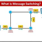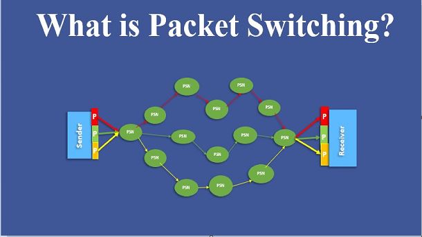
The basic approach is not much different from message switching. It is also based on the same ‘store-and-forward’ approach. However, to overcome the limitations of message switching, messages are divided into subsets of equal length called packets. This approach was developed for long-distance data communication (1970) and it has evolved over time. In packet switching approach, data are transmitted in short packets (few Kbytes). A long message is broken up into a series of packets as shown in Fig. Every packet contains some control information in its header, which is required for routing and other purposes.

A message is divided into a number of equal length short packets
Main difference between Packet switching and Circuit Switching is that the communication lines are not dedicated to passing messages from the source to the destination. In Packet Switching, different messages (and even different packets) can pass through different routes, and when there is a “dead time” in the communication between the source and the destination, the lines can be used by other sources.
There are two basic approaches commonly used to packet Switching: virtual-circuit packet switching and datagram packet switching. In virtual-circuit packet switching a virtual circuit is made before actual data is transmitted, but it is different from circuit switching in a sense that in circuit switching the call accept signal comes only from the final destination to the source while in case of virtual-packet switching this call accept signal is transmitted between each adjacent intermediate node as shown in Fig. Other features of virtual circuit packet switching are discussed in the following subsection.
Virtual Circuit Packet Switching Networks
An initial setup phase is used to set up a route between the intermediate nodes for all the packets passed during the session between the two end nodes. In each intermediate node, an entry is registered in a table to indicate the route for the connection that has been set up. Thus, packets passed through this route, can have short headers, containing only a virtual circuit identifier (VCI), and not their destination. Each intermediate node passes the packets according to the information that was stored in it, in the setup phase. In this way, packets arrive at the destination in the correct sequence, and it is guaranteed that essentially there will not be errors. This approach is slower than Circuit Switching, since different virtual circuits may compete over the same resources, and an initial setup phase is needed to initiate the circuit. As in Circuit Switching, if an intermediate node fails, all virtual circuits that pass through it are lost. The most common forms of Virtual Circuit networks are X.25 and Frame Relay, which are commonly used for public data networks (PDN).

Virtual circuit packet switching technique