Introduction
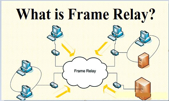
Frame Relay is a high-performance WAN protocol that operates at the physical and data link layers of the OSI reference model. Frame Relay originally was designed for use across Integrated Services Digital Network (ISDN) interfaces. Today, it is used over a variety of other network interfaces as well. Frame Relay is a simplified form of Packet Switching, similar in principle to X.25, in which synchronous frames of data are routed to different destinations depending on header information. The biggest difference between Frame Relay and X.25 is that X.25 guarantees data integrity and network managed flow control at the cost of some network delays. Frame Relay switches packets end to end much faster, but there is no guarantee of data integrity at all.
As line speeds have increased from speeds below 64kbps to T1/E1 and beyond, the delays inherent in the store-and-forward mechanisms of X.25 become intolerable. At the same time, improvements in digital transmission techniques have reduced line errors to the extent that node-to-node error correction throughout the network is no longer necessary. The vast majority of Frame Relay traffic consists of TCP/IP or other protocols that provide their own flow control and error correction mechanisms. Much of this traffic is fed into the Internet, another packet switched network without any built-in error control.
Because Frame Relay does not ‘care’ whether the frame it is switching is error-free or not, a Frame Relay node can start switching traffic out onto a new line as soon as it has read the first two bytes of addressing information at the beginning of the frame. Thus a frame of data can travel end-to-end, passing through several switches, and still arrive at its destination with only a few bytes’ delay. These delays are small enough that network latency under Frame Relay is not noticeably different from direct leased line connections. As a result, the performance of a Frame Relay network is virtually identical to that of a leased line, but because most of the network is shared, costs are lower.
Frame Relay is an example of a packet-switched technology. Packet-switched networks enable end stations to dynamically share the network medium and the available bandwidth. The following two techniques are used in packet-switching technology:
· Variable-length packets
· Statistical multiplexing
Variable-length packets are used for more efficient and flexible data transfers. These packets are switched between the various segments in the network until the destination is reached.
Statistical multiplexing techniques control network access in a packet-switched network. The advantage of this technique is that it accommodates more flexibility and more efficient use of bandwidth. Most of today’s popular LANs, such as Ethernet and Token Ring, are packet-switched networks.
Frame Relay Devices
Devices attached to a Frame Relay WAN fall into the following two general categories:
· Data terminal equipment (DTE)
· Data circuit-terminating equipment (DCE)
DTEs generally are considered to be terminating equipment for a specific network and typically are located on the premises of a customer. In fact, they may be owned by the customer. Examples of DTE devices are terminals, personal computers, routers, and bridges.
DCEs are carrier-owned internetworking devices. The purpose of DCE equipment is to provide clocking and switching services in a network, which are the devices that actually transmit data through the WAN. In most cases, these are packet switches.
The connection between a DTE device and a DCE device consists of both a physical layer component and a link layer component. The physical component defines the mechanical, electrical, functional, and procedural specifications for the connection between the devices. One of the most commonly used physical layer interface specifications is the recommended standard (RS)-232 specification. The link layer component defines the protocol that establishes the connection between the DTE device, such as a router, and the DCE device, such as a switch.
Virtual Circuits
Frame Relay is a virtual circuit network, so it doesn’t use physical addresses to define the DTEs connected to the network. Frame Relay provides connection-oriented data link layer communication. This means that a defined communication exists between each pair of devices and that these connections are associated with a connection identifier. However, virtual circuit identifiers in Frame relay operate at the data link layer, in contrast with X.25, where they operate at the network layer. This service is implemented by using a Frame Relay virtual circuit, which is a logical connection created between two data terminal equipment (DTE) devices across a Frame Relay packet-switched network (PSN).
Virtual circuits provide a bidirectional communication path from one DTE device to another and are uniquely identified by a data-link connection identifier (DLCI). A number of virtual circuits can be multiplexed into a single physical circuit for transmission across the network. This capability often can reduce the equipment and network complexity required to connect multiple DTE devices.
A virtual circuit can pass through any number of intermediate DCE devices (switches) located within the Frame Relay PSN. Before going into the details of DLCI let us first have a look at the two types of Frame Relay Circuits, namely: switched virtual circuits (SVCs) and permanent virtual circuits (PVCs).
Switched Virtual Circuits
Switched virtual circuits (SVCs) are temporary connections used in situations requiring only sporadic data transfer between DTE devices across the Frame Relay network. A communication session across an SVC consists of the following four operational states:
· Call setup—The virtual circuit between two Frame Relay DTE devices is established.
· Data transfer—Data is transmitted between the DTE devices over the virtual circuit.
· Idle—The connection between DTE devices is still active, but no data is transferred. If an SVC remains in an idle state for a defined period of time, the call can be terminated.
· Call termination—The virtual circuit between DTE devices is terminated.
After the virtual circuit is terminated, the DTE devices must establish a new SVC if there is additional data to be exchanged. It is expected that SVCs will be established, maintained, and terminated using the same signalling protocols used in ISDN.
Permanent Virtual Circuits
Permanent virtual circuits (PVCs) are permanently established connections that are used for frequent and consistent data transfers between DTE devices across the Frame Relay network. Communication across PVC does not require the call setup and termination states that are used with SVCs. PVCs always operate in one of the following two operational states:
· Data transfer: Data is transmitted between the DTE devices over the virtual circuit.
· Idle: The connection between DTE devices is active, but no data is transferred.
Unlike SVCs, PVCs will not be terminated under any circumstances when in an idle state. DTE devices can begin transferring data whenever they are ready because the circuit is permanently established.
Data-Link Connection Identifier (DLCI)
Frame Relay virtual circuits are identified by data-link connection identifiers (DLCIs). DLCI values typically are assigned by the Frame Relay service provider (for example, the telephone company). Frame Relay DLCIs have local significance, which means that their values are unique in the LAN, but not necessarily in the Frame Relay WAN. The local DTEs use this DLCI to send frames to the remote DTE.


Figure DLCIs connection between different DTEs
Figure shows the assignments of DLCIs, 3 connections have been shown namely, between A to D, D to E, and D to B. Point Here to be noted is that connection in fig.(a) and in fig.(c) uses the same DLCI, this can be done because these DLCIs are used by local DTEs. Bothe the connections are valid as they define different virtual circuits originating from different DTEs. DLCI=15 Figure 4.5.1 DLCIs connection between different DTEs.