Token BUS: A Brief History
Although Ethernet was widely used in the offices, but people interested in factory automation did not like it because of the probabilistic MAC layer protocol. They wanted a protocol which can support priorities and has predictable delay. These people liked the conceptual idea of Token Ring network but did not like its physical implementation as a break in the ring cable could bring the whole network down and ring is a poor fit to their linear assembly lines. Thus a new standard, known as Token bus, was developed, having the robustness of the Bus topology, but the known worst-case behaviour of a ring. Here stations are logically connected as a ring but physically on a Bus and follows the collision-free token passing medium access control protocol. So the motivation behind token bus protocol can be summarized as:
· The probabilistic nature of CSMA/ CD leads to uncertainty about the delivery time; which created the need for a different protocol
· The token ring, on the hand, is very vulnerable to failure.
· Token bus provides deterministic delivery time, which is necessary for real time traffic.
· Token bus is also less vulnerable compared to token ring.
Functions of a Token Bus
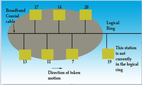
It is the technique in which the station on bus or tree forms a logical ring, that is the stations are assigned positions in an ordered sequence, with the last number of the sequence followed by the first one as shown in Fig. Each station knows the identity of the station following it and preceding it.

Token Bus topology
A control packet known as a Token regulates the right to access. When a station receives the token, it is granted control to the media for a specified time, during which it may transmit one or more packets and may poll stations and receive responses when the station is done, or if its time has expired then it passes token to next station in logical sequence. Hence, steady phase consists of alternate phases of token passing and data transfer.
The MAC sublayer consists of four major functions: the interface machine (IFM), the access control machine (ACM), the receiver machine (RxM) and the transmit machine (TxM).
IFM interfaces with the LLC sublayer. The LLC sublayer frames are passed on to the ACM by the IFM and if the received frame is also an LLC type, it is passed from RxM component to the LLC sublayer. IFM also provides quality of service.
The ACM is the heart of the system. It determines when to place a frame on the bus, and responsible for the maintenance of the logical ring including the error detection and fault recovery. It also cooperates with other stations ACM’s to control the access to the shared bus, controls the admission of new stations and attempts recovery from faults and failures.
The responsibility of a TxM is to transmit frame to physical layer. It accepts the frame from the ACM and builds a MAC protocol data unit (PDU) as per the format.
The RxM accepts data from the physical layer and identifies a full frame by detecting the SD and ED (start and end delimiter). It also checks the FCS field to validate an error free transmission.
Comments are closed